Menu
Physics Lesson 14.7.2 - Capacitors
Please provide a rating, it takes seconds and helps us to keep this resource free for all to use
Welcome to our Physics lesson on Capacitors, this is the second lesson of our suite of physics lessons covering the topic of Capacitance and Capacitors, you can find links to the other lessons within this tutorial and access additional physics learning resources below this lesson.
Capacitors
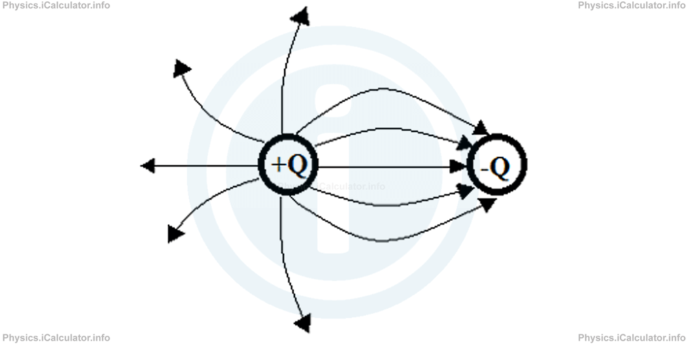
A capacitor is a system composed by two conductors separated by a dielectric (usually air). The simplest and smallest capacitor possible would be a proton and an electron at a certain distance from each other. Two oppositely charged spheres not in contact are another example of capacitor.
Most capacitors however are of three designs:
- two parallel plates with some space between them,
- cylindrical capacitors, and
- concentric spheres
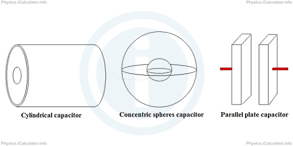
Cylindrical capacitors are the most widespread type of capacitors encountered in electronic devices. However, when explaining capacitor properties, it is more suitable to start with parallel plate capacitors, as they are easier to understand.
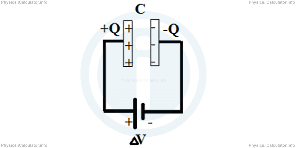
Once the capacitor is charged, the two conductors carry equal but opposite charges. Therefore, we consider the charge of one plate only when calculating the capacitance of a capacitor.
Parallel Plate Capacitor
A parallel plate capacitor consists of two identical parallel plates, each of them having an area A and separated by a distance d between them.
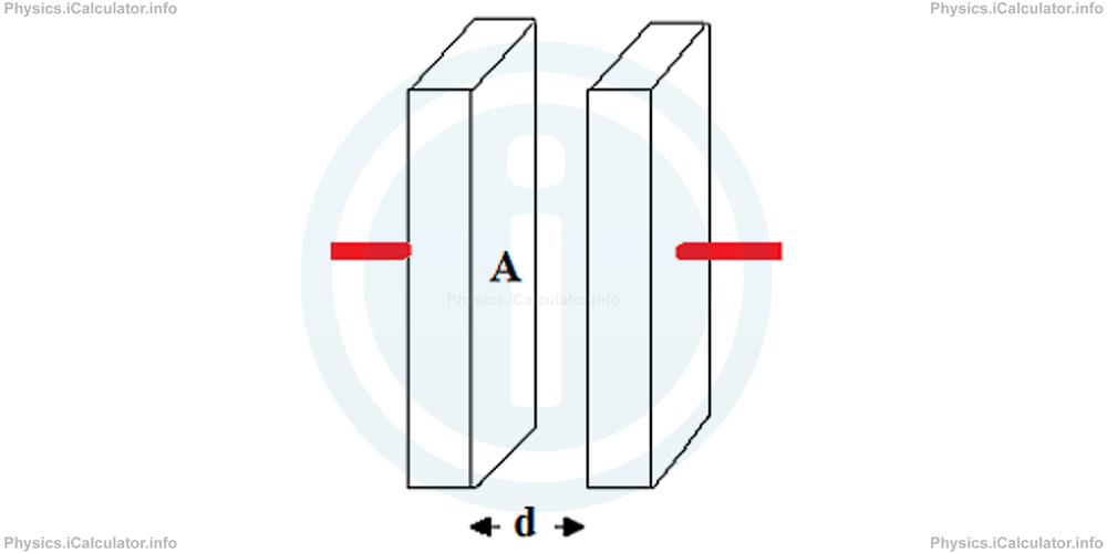
When we connect the two plates with the poles of a battery, the capacitor is charged as discussed in the previous tutorials during the calculation of electric potential energy of a charge inside a uniform field. In such a system, the plate connected to the positive terminal of battery is charged positively (+Q) while the plate connected to the negative terminal of battery is charged negatively (-Q).
Let's see what are the factors affecting the capacitance of a parallel plate capacitor.
- When area A of plates increases, the capacitor is able to carry more charges than before. Thus, capacitance of parallel plate capacitors is proportional to the plates' area.
- If the distance d between plates increases, they are not able to induce as much charges as before because their attracting ability decreases. Therefore, capacitance is inversely proportional to the distance between plates.
Thus, we can write
As we have stated earlier, we must multiply a proportion by a constant to turn it into equation. The constant used here is the already discussed electric constant ϵ0. Hence, we obtain for the capacity of a parallel plate capacitor
The above formula is true in vacuum (and with a good approximation, in air). When the capacitor is placed inside a dielectric, we must include another factor in the formula. It is known as the dielectric constant ϵ, otherwise known as relative permittivity, which affects the value of capacitance, more precisely it increases the capacitance. Hence, we obtain
The relative permittivity of vacuum is 1, that of air very close to 1 (more precisely 1.00054) while for the other dielectrics, its value is greater than 1.
The unit of electric constant ϵ0 is Farad / metre. In the previous tutorial, we have mentioned another unit for ϵ0 that is C2/N × m2. Since these two units represent the same quantity, we obtain
Or
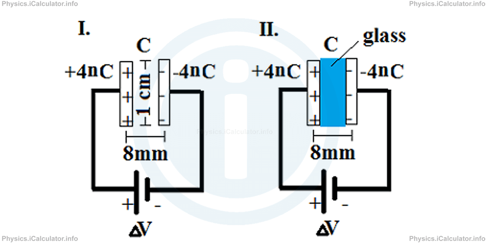
Example 2
Two square shaped parallel plates of a capacitor are charged by +4nC and -4nC respectively when connected to the terminals of a powerful battery. The sides of each plate are 1 cm long.
- What is the capacitance if the plates are 8mm apart?
- What is the potential difference of battery?
- What will the new capacitance be if we place an 8mm thick class between the plates? The relative permittivity (dielectric constant) of glass is 10.
Solution 2
a) Let's convert the units into the standard form first. We have Q = 4 nC = 4 × 10⁻⁹ C, d = 8 mm = 8 × 10⁻³ m and L = 1 cm = 10-2 m.
Since the plates have a squared shape, their area is
= (10-2 m)2
= 10-4 m2
Thus, the capacitance is
= 8.85 × 10⁻¹² F/m × 10-4 m2/8 × 10-3 m
= 1.1 × 10⁻¹³ F
= 0.11 pF
b) The potential difference of battery is calculated by using the standard formula of capacitors. We have
Rearranging, we obtain for the potential difference of battery:
= 4 × 10⁻⁹ C/1.1 × 10-13 F
= 3.6 × 10⁴ V
= 36 kV
c) If glass is placed between the plates, we must simply multiply the capacitance found at (a) by the relative permittivity of glass. Thus,
= ϵ × C
= 10 × 1.1 × 10-13 F
= 1.1 × 10⁻¹² F
= 1.1 pF
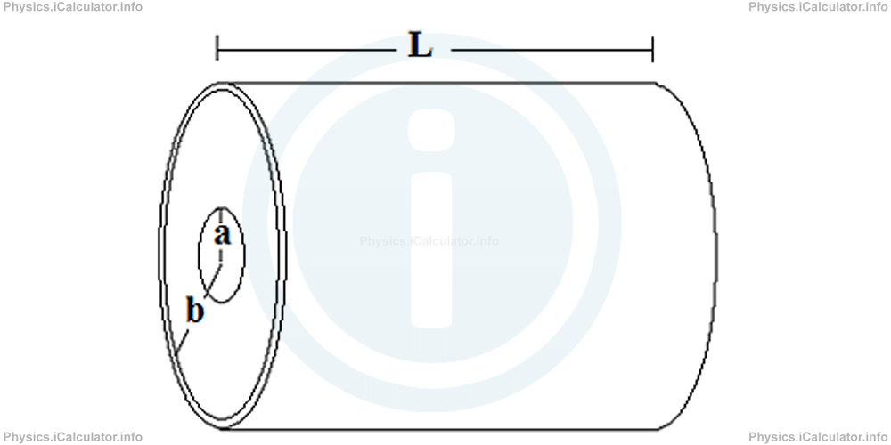
Cylindrical-Shaped Capacitor
A cylindrical-shaped capacitor is a system composed by two coaxial cylinders. The parameters of a cylindrical capacitor are:
- Length, L
- Radius of the smaller cylinder a, and
- Radius of the smaller cylinder b.
Using integration methods (which are not worth to discuss here), we obtain for the capacitance of a cylindrical-shaped capacitor:
From mathematics, it is known that if
Also, it is known that
When the base of logarithm is e (Euler number = 2.71828), the symbol of logarithm is written as ln (natural logarithm) instead of log. You can find the values of log and ln using a scientific calculator.
Example 3
A cylindrical-shaped capacitor has the length of the smaller radius equal to 6 mm and that of the larger radius equal to 1 cm. The capacitor is 2 cm long and is placed inside water in 20°C, whose dielectric constant for this temperature is 80. Calculate the capacitance of this cylindrical capacitor. Refer to the figure shown above in theory for illustration.
Solution 3
Let's write the clues first. We have
a = 6 mm = 6 × 10⁻³ m
b = 1 cm = 1 × 10⁻² m = 10 × 10-3 m
L = 2 cm = 2 × 10⁻² m
ϵ = 80
ϵ0 = 8.85 × 10⁻¹² F/m
C = ?
Applying the formula of cylindrical-shaped capacitor, we obtain
= 2 × 3.14 × 80 × 8.85 × 10-12 × 2 × 10-2/ln 10 × 10-3/6 × 10-3
= 8.89 × 10⁻¹¹/ln 10/6
= 8.89 × 10⁻¹¹/ln 10 - ln 6
= 8.89 × 10⁻¹¹/2.3 - 1.8
= 8.89 × 10⁻¹¹/0.5
= 1.78 × 10⁻¹⁰ F
= 178 pF
Concentric Spheres Capacitor
A spherical capacitor is a system composed by two concentric spheres of radius a (the smallest) and b (the largest).
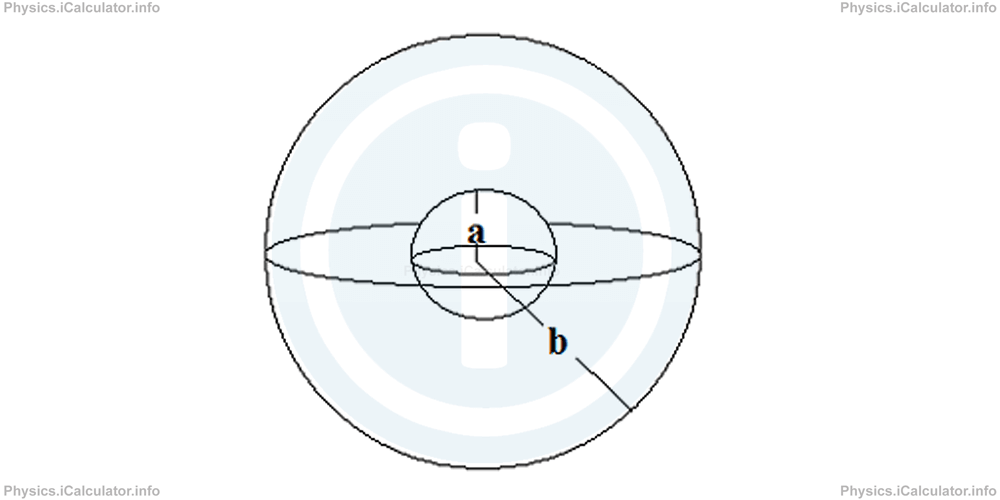
Again, using the integration methods, we obtain for the capacitance of such capacitor:
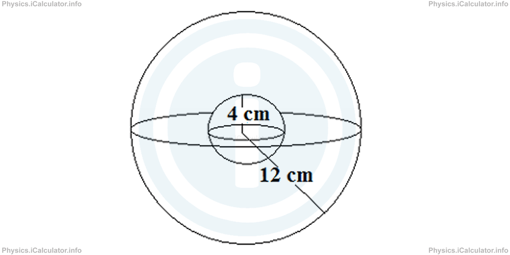
Example 4
A spherical capacitor has the radii of the two concentric spheres 4 cm and 12 cm respectively. What is the capacitance if the capacitor
- Operates in dry environment
- Operates immersed inside a methanol container of dielectric constant equal to 30.
Solution 4
a) "Operates in dry environment" means "operates in air", whose dielectric constant is taken as 1. Given that a = 4 cm = 0.04 m and b = 12 cm = 0.12 m, we have
= 4 × 3.14 × 1 × 8.85 × 10-12/1/0.04 - 1/0.12
= 111.156 × 10⁻¹¹/3 - 1/0.12
= 6.669 × 10⁻¹¹ F
= 666.9 nF
You have reached the end of Physics lesson 14.7.2 Capacitors. There are 4 lessons in this physics tutorial covering Capacitance and Capacitors, you can access all the lessons from this tutorial below.
More Capacitance and Capacitors Lessons and Learning Resources
Whats next?
Enjoy the "Capacitors" physics lesson? People who liked the "Capacitance and Capacitors lesson found the following resources useful:
- Capacitors Feedback. Helps other - Leave a rating for this capacitors (see below)
- Electrostatics Physics tutorial: Capacitance and Capacitors. Read the Capacitance and Capacitors physics tutorial and build your physics knowledge of Electrostatics
- Electrostatics Revision Notes: Capacitance and Capacitors. Print the notes so you can revise the key points covered in the physics tutorial for Capacitance and Capacitors
- Electrostatics Practice Questions: Capacitance and Capacitors. Test and improve your knowledge of Capacitance and Capacitors with example questins and answers
- Check your calculations for Electrostatics questions with our excellent Electrostatics calculators which contain full equations and calculations clearly displayed line by line. See the Electrostatics Calculators by iCalculator™ below.
- Continuing learning electrostatics - read our next physics tutorial: Electric Charges. Conductors and Insulators
Help others Learning Physics just like you
Please provide a rating, it takes seconds and helps us to keep this resource free for all to use
We hope you found this Physics lesson "Capacitance and Capacitors" useful. If you did it would be great if you could spare the time to rate this physics lesson (simply click on the number of stars that match your assessment of this physics learning aide) and/or share on social media, this helps us identify popular tutorials and calculators and expand our free learning resources to support our users around the world have free access to expand their knowledge of physics and other disciplines.