Menu
Physics Lesson 14.7.3 - Combination of Capacitors
Please provide a rating, it takes seconds and helps us to keep this resource free for all to use
Welcome to our Physics lesson on Combination of Capacitors, this is the third lesson of our suite of physics lessons covering the topic of Capacitance and Capacitors, you can find links to the other lessons within this tutorial and access additional physics learning resources below this lesson.
Combination of Capacitors
Capacitors have fixed values like most electric devices. This is because it is impossible to produce capacitors by demand. Certainly, we may try to insert dielectrics between the plates to change the capacitance but this process is too complicated. It is much easier to combine two or more capacitors in order to obtain the desired capacitance. Remember, we have used such a method when combining springs to obtain the desired spring constant. In that case, we used two main methods of spring combination: in series and in parallel. The same technique is also used to combine capacitors in an electric circuit.
a) Series Combination of Capacitors
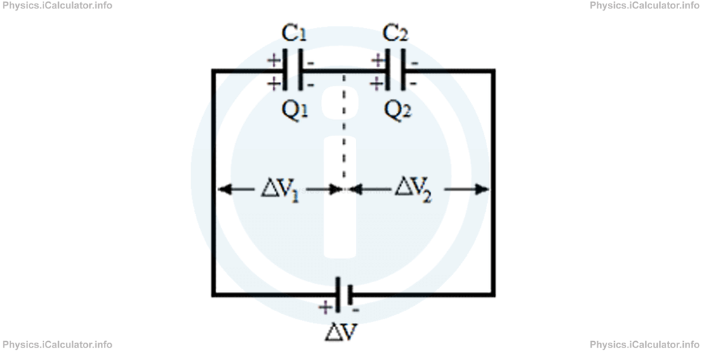
Two or more capacitors are connected in series if they are placed one after another in the same conducting wire of an electric circuit, as shown in the figure below.
The system of two capacitors connected in series operates as follows:
Initially, both capacitors are uncharged. When the right plate of the second capacitor C2 is connected to the negative terminal of battery, it gains a negative charge -Q2 and repels the positive charges on the other plate of the same capacitor, producing a positive charge +Q2 on it. The charges -Q2 and +Q2 are opposite in sign but equal in magnitude. The positive charges on the left plate of C2 repel the negative charges on the conducting wire as far as possible, i.e. on the right plate of C1, producing a negative charge -Q1 on it. As a result, a positive charge +Q1 is created on the other plate of the same capacitor. Since there is the same connecting wire between the two capacitors, the charge distribution between these two capacitors is even, as all negative charges that accumulate to the right plate of Q1 leave the same number of unpaired positive charges on the left plate of Q2. Therefore, we can write for the two capacitors connected in series
From the figure, it is clear that the total potential difference ΔVs produced by the source (the battery) is divided in two parts, ΔV1 and ΔV2, i.e.
Substituting the quantities contained in the capacitor formula C = Q / ΔV in the above equation, we obtain after rearranging
Simplifying Q from both sides, we obtain for the capacitance of the series combination of a system composed by two capacitors
We can extend the above rule for more than two capacitors as well, that is
It is clear that when two capacitors are connected in series, the total capacitance of the system is smaller than that of a single capacitor. Therefore, series combination setups are used when in a circuit, a smaller capacitance than that of the individual capacitors available is needed.
Example 5
A system composed by two capacitors connected in series is shown in the figure below.
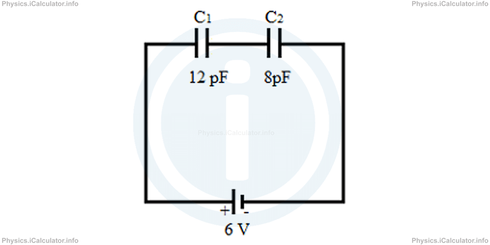
What is the total charge stored in this system?
Solution 5
First, we must work out the capacitance of the system of capacitors. Since they are connected in series, we have
1/Cs = 1/12 + 1/8
= 2 + 3/24
= 5/24
Thus,
= 4.8 pF
= 4.8 × 10⁻¹² F
Now, let's use the formula of capacitance to find the electric charge of the system. We have
= 4.8 × 10-12 F × 6 V
= 28.8 × 10⁻¹² C
= 28.8 pC
b) Parallel Combination of Capacitors
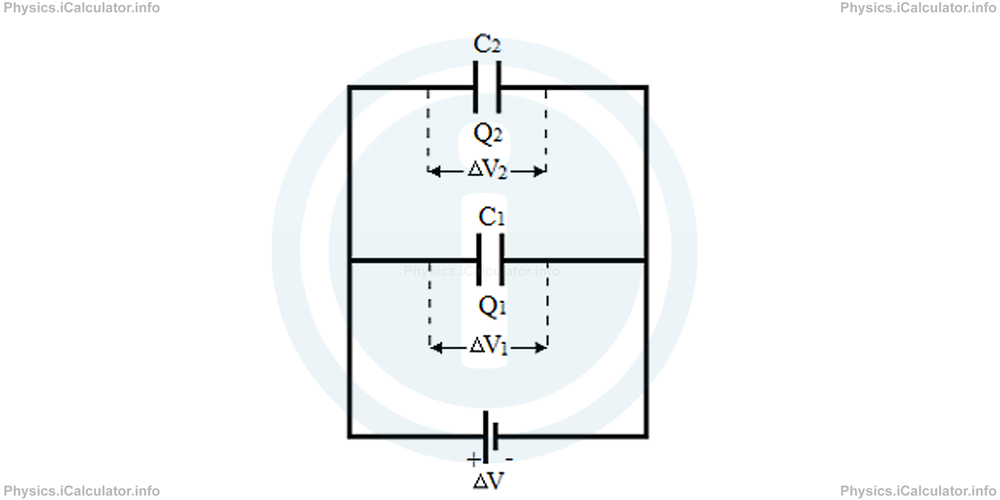
If two or more capacitors are connected in two or more different branches of the same circuit, which have the same starting and ending point, we say they are connected in parallel, as shown in the figure below.
The system of two capacitors connected in series operates as follows:
Initially, both capacitors are uncharged. If a potential difference ΔV is applied across these capacitors, the plates are charged oppositely, depending on the terminal of battery they are connected with. Since these plates are connected to the same source of electricity, they have the same potential difference, which is equal to the potential difference of battery. We have
The battery charges the capacitors in accordance to their capacities. Therefore, we can write for the total electric charge stored in the two capacitors
Applying the capacitance formula C = Q/ΔV in the last equation, we obtain after rearranging:
Simplifying ΔV from both sides, we obtain for the capacitance of a parallel system of two capacitors:
This formula is also true for a system composed more than two capacitors connected in parallel. Thus, we have
As you see, the total capacitance of a parallel system is greater than the capacitance of each single capacitor. Therefore, such a combination is used when the capacitors available are smaller than needed.
Example 6
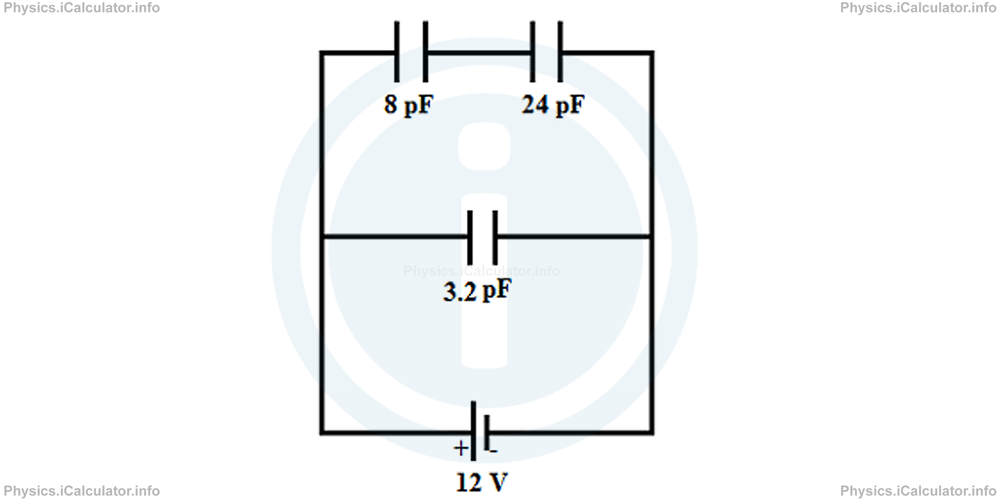
A system composed by three capacitors is connected to a 12 V battery as shown in the figure.
Calculate:
- Capacitance of the system
- The total charge stored in the system
- The electric charge stored in each capacitor
Solution 6
First, let's appoint a symbol to each capacitor and write the corresponding capacitances. We can write
C2 = 8 pF = 8 × 10-12 F
C3 = 12 pF = 12 × 10-12 F
Also, we have ΔV = 12 V.
a) First, we must find the capacitance of the series branch of capacitors that is the equivalent capacitance of C2 and C3. Thus,
= 1/8 + 1/12
= 3 + 2/24
= 5/24
Hence,
= 4.8 pF
= 4.8 × 10⁻¹² F
Now, we can assume there are only two capacitors connected in the circuit: C1 and Cp which are in parallel, as shown below.
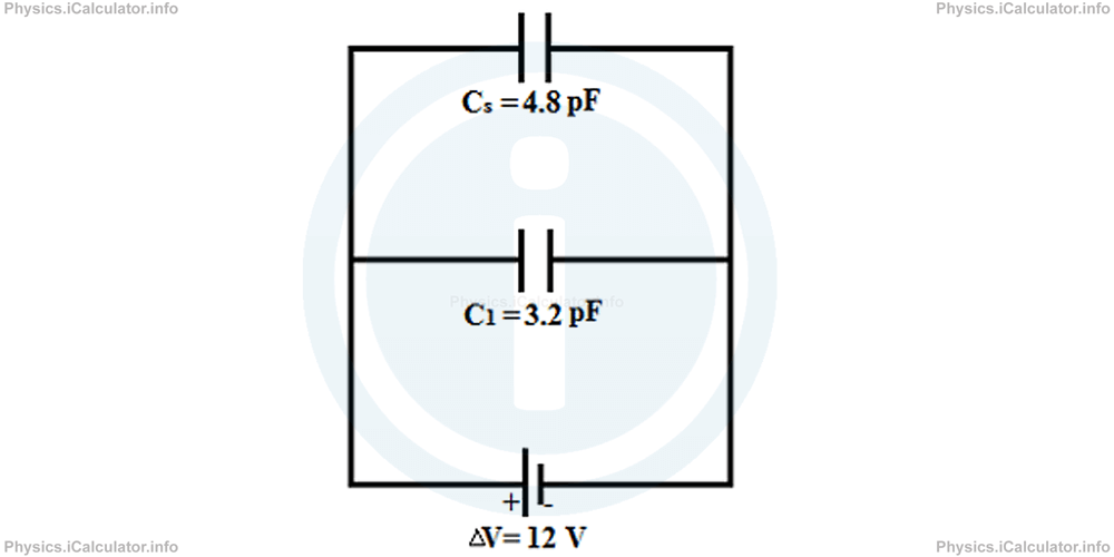
Therefore, we obtain for the total capacitance of the system:
= 3.2 pF + 4.8 pF
= 8 pF
= 8 × 10-12 F
b) The total charge in the system is calculated by using the capacitance formula. We have
= 8 × 10-12 F × 12 V
= 96 × 10-12 C
= 96 nC
c) The charge distribution is in accordance with the capacitance of each branch in the parallel section, in which the same potential difference (12 V) is applied. Also, we know that the electric charge is the same for each capacitor in a series combination of capacitors. Thus, we have
= 3.2 × 10-12 F × 12 V
= 38.4 × 10⁻¹² C
= 38.4 pC
Also,
= 4.8 × 10-12 F × 12 V
= 57.6 × 10⁻¹² C
= 57.6 pC
Remark!
It must be noted that when the capacitance of a system increases, its common potential difference ΔVcom decreases. This conclusion derives from the fact that capacitance and potential difference are inversely proportional for constant charge (C = Q / ΔV, so C × ΔV = C = constant). Let's explain this point through an example.
Example 7
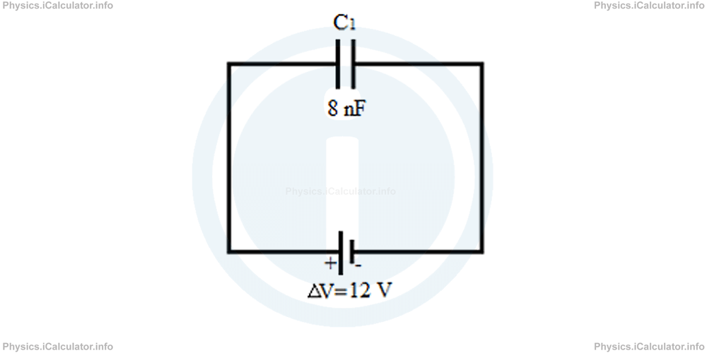
The capacitor C1 is charged by means of a 24 V battery as shown in the figure.
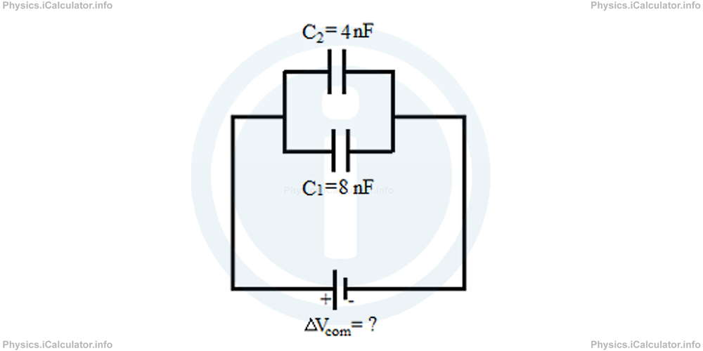
The capacitor C1 is then connected in parallel with an uncharged capacitor C2 of capacitance 24 nF as shown in the other figure shown below.
Calculate:
- The common capacitance after the capacitors are connected in parallel.
- The final charges in each capacitor.
Solution 7
a) The charge in the 8 nF capacitor when it is alone in the circuit is
= 8 nF × 12 V
= 96 nC
Since the capacitors in the second figure are connected in parallel, the total charge is distributed in two branches. Thus, we have
Here the total charge Qtot corresponds to the previous charge of Q1 since the capacitor Q2 was initially uncharged.
In addition, the total capacitance of this parallel system of capacitors is
= 8 nF + 4 nF
= 12 nF
Therefore, the common potential difference after the capacitor C2 is added in the system is
= 96 nC/12 nF
= 8 V
As you see, the new common difference is smaller than the initial potential difference when a single capacitor was present in the circuit.
b) We can apply the capacitance formula for each capacitor separately to find the charge stored in them. Thus, we obtain for the new charges on the two capacitors:
= 8 nF × 8 V
= 64 nC
and
= 4 nF × 8 V
= 32 nC
As you see, the charge is conserved as the total charge after is equal to the total charge before the second capacitor is connected in the circuit (both are 96 nC).
You have reached the end of Physics lesson 14.7.3 Combination of Capacitors. There are 4 lessons in this physics tutorial covering Capacitance and Capacitors, you can access all the lessons from this tutorial below.
More Capacitance and Capacitors Lessons and Learning Resources
Whats next?
Enjoy the "Combination of Capacitors" physics lesson? People who liked the "Capacitance and Capacitors lesson found the following resources useful:
- Combination Feedback. Helps other - Leave a rating for this combination (see below)
- Electrostatics Physics tutorial: Capacitance and Capacitors. Read the Capacitance and Capacitors physics tutorial and build your physics knowledge of Electrostatics
- Electrostatics Revision Notes: Capacitance and Capacitors. Print the notes so you can revise the key points covered in the physics tutorial for Capacitance and Capacitors
- Electrostatics Practice Questions: Capacitance and Capacitors. Test and improve your knowledge of Capacitance and Capacitors with example questins and answers
- Check your calculations for Electrostatics questions with our excellent Electrostatics calculators which contain full equations and calculations clearly displayed line by line. See the Electrostatics Calculators by iCalculator™ below.
- Continuing learning electrostatics - read our next physics tutorial: Electric Charges. Conductors and Insulators
Help others Learning Physics just like you
Please provide a rating, it takes seconds and helps us to keep this resource free for all to use
We hope you found this Physics lesson "Capacitance and Capacitors" useful. If you did it would be great if you could spare the time to rate this physics lesson (simply click on the number of stars that match your assessment of this physics learning aide) and/or share on social media, this helps us identify popular tutorials and calculators and expand our free learning resources to support our users around the world have free access to expand their knowledge of physics and other disciplines.