Menu
Physics Lesson 16.17.1 - Electric Power as a Rate of Electric Energy Transfer
Please provide a rating, it takes seconds and helps us to keep this resource free for all to use
Welcome to our Physics lesson on Electric Power as a Rate of Electric Energy Transfer, this is the first lesson of our suite of physics lessons covering the topic of Power in an Alternating Circuit. Transformers, you can find links to the other lessons within this tutorial and access additional physics learning resources below this lesson.
Electric Power as a Rate of Electric Energy Transfer
As explained in tutorial 5.5 "Power and Efficiency", power is the work done by system in the unit time. In other words, power as a generalized concept, is the rate of useful energy transfer - a process that brings a change in the energy of the system, i.e.
In addition, from the definition of work (the energy used by a system to displace an object or to transfer heat to it), we can include the thermal energy transfer (heat energy therefore) in the definition of power. The advantage of this approach is observed when dealing with electric power. We all know that electricity (electrical energy) is used for several purposes where one of the most important applications is to dissipate heat energy in the environment through a resistor. When considering also the time interval during which this heat energy is dissipated in the environment, we obtain the concept of useful electric power (explained in tutorial 15.6 "Electric Power and Efficiency"), which is found by applying the Joule's Law, i.e.
The above equation is applied when calculating the power delivered by an energy-consuming device, such as a resistor. When calculating the power delivered by the source, we must replace potential difference ΔV with the electromotive force ε in the equation of electrical power, i.e.
In DC circuits we don't have any difficulty in calculating the power delivered by the source (input or total power) and that of any circuit component (output or useful power) because the values of emf, current and voltage are constant. In this way, the efficiency of circuit (the part of the total energy converted in the desired form, i.e. as useful energy) is calculated by
In AC circuits however, the discussion about electrical power is more complicated as both current and voltage in circuit are not constant; they both vary in a sinusoidal fashion. We can transform the equation
in such a way that one of the above quantities is expressed in terms of the other or through a constant. Hence, giving that in DC circuits
= I ∙ I ∙ R
= I2 ∙ R
we use the same approach in AC circuits as well, to eliminate the induced emf from the formula. Thus, we write
= i(t) ∙ [i(t) ∙ R]
= i2 (t) ∙ R
where R is the resistance of the AC circuit.
In this way, since current in an AC circuit as a function of time, is
we obtain for the power dissipated in such a circuit:
or
It is not necessary to calculate the power through this method however; we can use the concept of average power to simplify this process. For this, we must write the rms current instead of the maximum current in the above formula. In this way, we obtain for the average power in an AC circuit
= irms2 ∙ R
= (imax/√2)2 ∙ R
= imax2 ∙ R/2
= Pmax/2
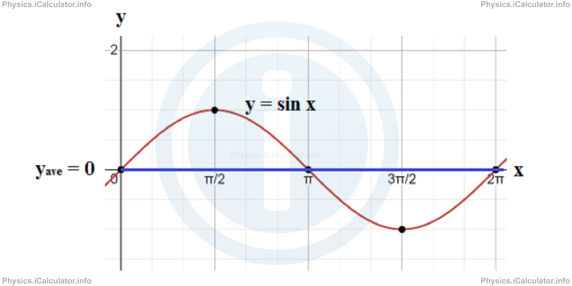
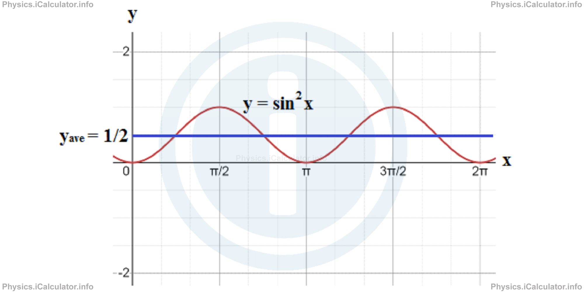
The above result is also proven by considering the fact that the average value of y = sin2 x function during a complete cycle is 1/2 despite the average value of y = sin x is zero. This is clarified through the two graphs below.
The electrical measuring devices such as ammeter and voltmeter are calibrated in such a way that they measure the average (rms) voltage and current instead of their maximum values. Thus, for example if a multimeter (a device that includes both an ammeter and a voltmeter) shows the values 4A and 220V, these are the average values of the corresponding quantities. If we want to known the amplitudes of current and voltage in the circuit, we write
= (4A) ∙ √2
= 5.66 A
and
= (220 V) ∙ √2
= 311.13 V
If we want to calculate the average power in the circuit, we obtain
= (4A) ∙ (220V)
= 880 W
The maximum power delivered by the circuit is obviously twice this value, i.e.
= (880 W) ∙ 2
= 1760 W
Indeed,
= (5.66 A) ∙ (311.13 V)
= 1760 W
If we consider all three quantities responsible for the impedance in the circuit, we obtain for the rms current
We can express the average power delivered in the circuit as
= εrms/Z ∙ irms ∙ R
= εrms ∙ irms ∙ R/Z
The quantity R/Z is the cosine of the phase constant φ discussed in the previous tutorial, i.e.
Hence, combining the last two equations, yields
= εrms ∙ irms ∙ cosφ
The 'cos φ' term is called "power factor." It is independent from the sign of the phase constant φ because cos φ = cos (-φ) for every value of φ.
The value of power factor is very important in maximizing the rate of energy supplied to a resistive load. To achieve this, the value of power factor must be as close to 1 as possible. This means the phase constant must be as close as possible to zero, i.e. the values of inductive and capacitive load must be very close to each other. Thus, for example if a circuit is more inductive than capacitive, we increase the capacitance in the circuit to balance the reactances. On the other hand, if the circuit is more capacitive than inductive, we decrease the capacitance by connecting an extra capacitor in the circuit (it is known that the total capacitance of a series combination of capacitors decreases the total capacitance in the system). After all, the main goal is to increase the power delivered in the circuit; no matter the method used.
Example 1
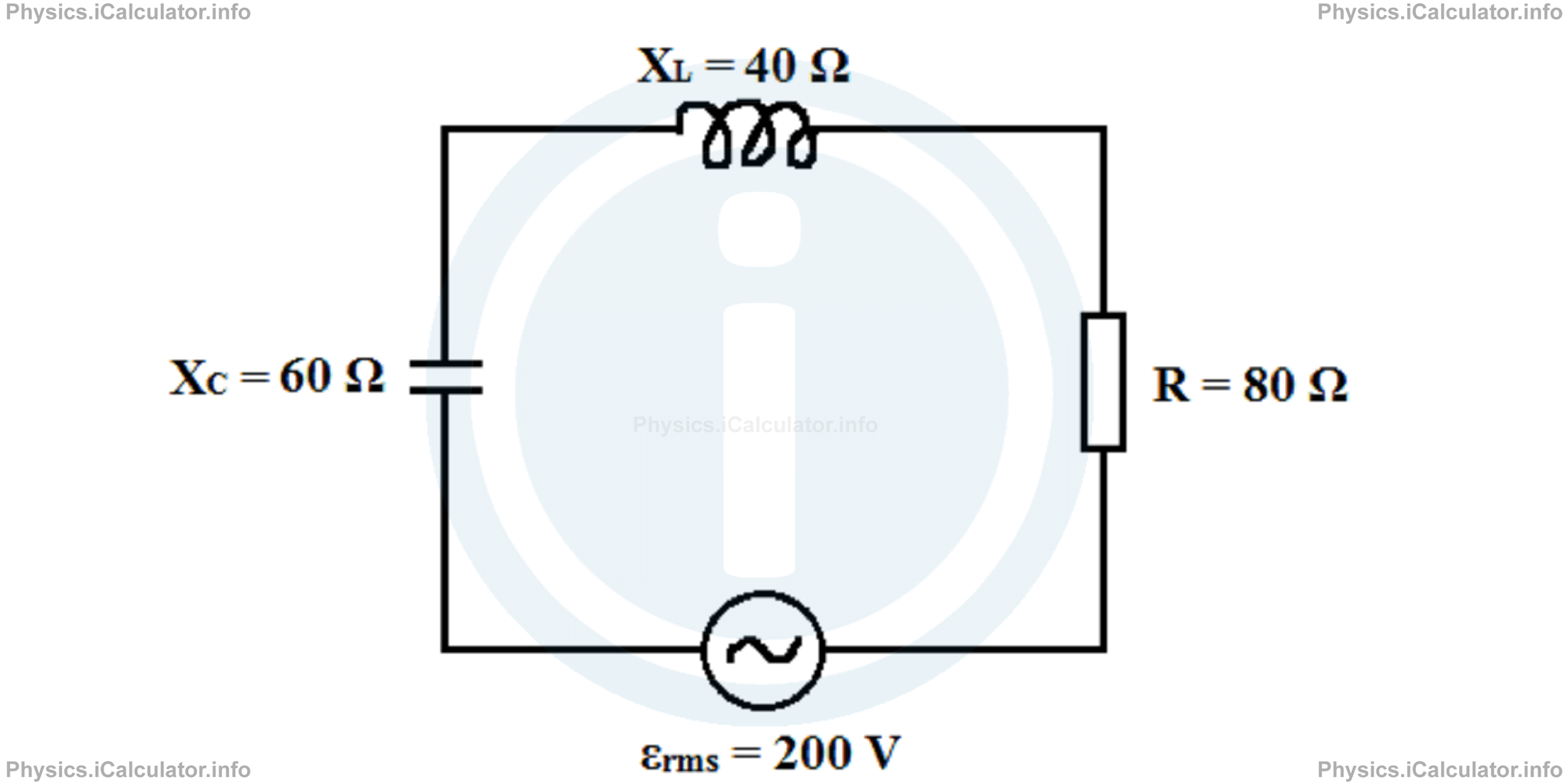
A series RLC circuit operating at fd = 50 Hz is shown in the figure below.
Calculate:
- The power factor and phase constant of the circuit
- The average rate at which the energy is dissipated in the circuit
- The extra capacitance needed to maximize the average power if the other parameters in the circuit are kept unchanged
Solution 1
- Let's calculate the impedance Z first. Thus, Z = √R2 + (XL-Xc )2The power factor therefore is
= √(80 Ω)2 + (40 Ω-60 Ω)2
= 82.5 Ωcosφ = R/ZHence, the phase constant is
= 80 Ω/82.5 Ω
= 0.97φ = cos-1 0.97Since XC > XL we must consider the negative value only. Thus, φ = - 0.246 rad.
= ±0.246 rad - First, we have to find the rms current flowing through the circuit. Thus, irms = εrms/ZThe average rate at which the energy is dissipated in the circuit means the average power delivered by the circuit. Thus, we have
= 200 V/82.5 Ω
= 2.424 A= εrms ∙ irms ∙ cos φ
= (200 V) ∙ (2.424 A) ∙ (0.97)
= 470.3 W - The average power is maximized if the circuit is in resonance, i.e. if XL = XC. This is achieved by decreasing the value of capacitance, i.e. by connecting a new capacitor in series to the given one. Since Xc = 1/ωd ∙ C = 1/(2π ∙ f ∙ C)we obtain for the actual capacitanceC = 1/2π ∙ f ∙ XcThe capacitance in the new conditions (when the circuit is in resonance) is obtained for
= 1/2 ∙ 3.14 ∙ (50 Hz) ∙ (60 Ω)
= 5.31 × 10⁻⁵ FXL = XcThus,XL = 1/2π ∙ f ∙ CnewThis means the extra capacitance added in the system is
Cnew = 1/2π ∙ f ∙ XL
= 1/2 ∙ 3.14 ∙ (50 Hz) ∙ (40 Ω)
= 7.96 × 10⁻⁵ FCextra = Cnew - C
= 7.96 × 10⁻⁵ F - 5.31 × 10⁻⁵ F
= 2.65 × 10⁻⁵ F
You have reached the end of Physics lesson 16.17.1 Electric Power as a Rate of Electric Energy Transfer. There are 3 lessons in this physics tutorial covering Power in an Alternating Circuit. Transformers, you can access all the lessons from this tutorial below.
More Power in an Alternating Circuit. Transformers Lessons and Learning Resources
Whats next?
Enjoy the "Electric Power as a Rate of Electric Energy Transfer" physics lesson? People who liked the "Power in an Alternating Circuit. Transformers lesson found the following resources useful:
- Rate Feedback. Helps other - Leave a rating for this rate (see below)
- Magnetism Physics tutorial: Power in an Alternating Circuit. Transformers. Read the Power in an Alternating Circuit. Transformers physics tutorial and build your physics knowledge of Magnetism
- Magnetism Revision Notes: Power in an Alternating Circuit. Transformers. Print the notes so you can revise the key points covered in the physics tutorial for Power in an Alternating Circuit. Transformers
- Magnetism Practice Questions: Power in an Alternating Circuit. Transformers. Test and improve your knowledge of Power in an Alternating Circuit. Transformers with example questins and answers
- Check your calculations for Magnetism questions with our excellent Magnetism calculators which contain full equations and calculations clearly displayed line by line. See the Magnetism Calculators by iCalculator™ below.
- Continuing learning magnetism - read our next physics tutorial: Maxwell Equations
Help others Learning Physics just like you
Please provide a rating, it takes seconds and helps us to keep this resource free for all to use
We hope you found this Physics lesson "Power in an Alternating Circuit. Transformers" useful. If you did it would be great if you could spare the time to rate this physics lesson (simply click on the number of stars that match your assessment of this physics learning aide) and/or share on social media, this helps us identify popular tutorials and calculators and expand our free learning resources to support our users around the world have free access to expand their knowledge of physics and other disciplines.
Magnetism Calculators by iCalculator™
- Angular Frequency Of Oscillations In Rlc Circuit Calculator
- Calculating Magnetic Field Using The Amperes Law
- Capacitive Reactance Calculator
- Current In A Rl Circuit Calculator
- Displacement Current Calculator
- Electric Charge Stored In The Capacitor Of A Rlc Circuit In Damped Oscillations Calculator
- Electric Power In A Ac Circuit Calculator
- Energy Decay As A Function Of Time In Damped Oscillations Calculator
- Energy Density Of Magnetic Field Calculator
- Energy In A Lc Circuit Calculator
- Faradays Law Calculator
- Frequency Of Oscillations In A Lc Circuit Calculator
- Impedance Calculator
- Induced Emf As A Motional Emf Calculator
- Inductive Reactance Calculator
- Lorentz Force Calculator
- Magnetic Dipole Moment Calculator
- Magnetic Field At Centre Of A Current Carrying Loop Calculator
- Magnetic Field In Terms Of Electric Field Change Calculator
- Magnetic Field Inside A Long Stretched Current Carrying Wire Calculator
- Magnetic Field Inside A Solenoid Calculator
- Magnetic Field Inside A Toroid Calculator
- Magnetic Field Produced Around A Long Current Carrying Wire
- Magnetic Flux Calculator
- Magnetic Force Acting On A Moving Charge Inside A Uniform Magnetic Field Calculator
- Magnetic Force Between Two Parallel Current Carrying Wires Calculator
- Magnetic Potential Energy Stored In An Inductor Calculator
- Output Current In A Transformer Calculator
- Phase Constant In A Rlc Circuit Calculator
- Power Factor In A Rlc Circuit Calculator
- Power Induced On A Metal Bar Moving Inside A Magnetic Field Due To An Applied Force Calculator
- Radius Of Trajectory And Period Of A Charge Moving Inside A Uniform Magnetic Field Calculator
- Self Induced Emf Calculator
- Self Inductance Calculator
- Torque Produced By A Rectangular Coil Inside A Uniform Magnetic Field Calculator
- Work Done On A Magnetic Dipole Calculator